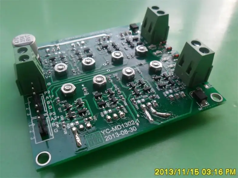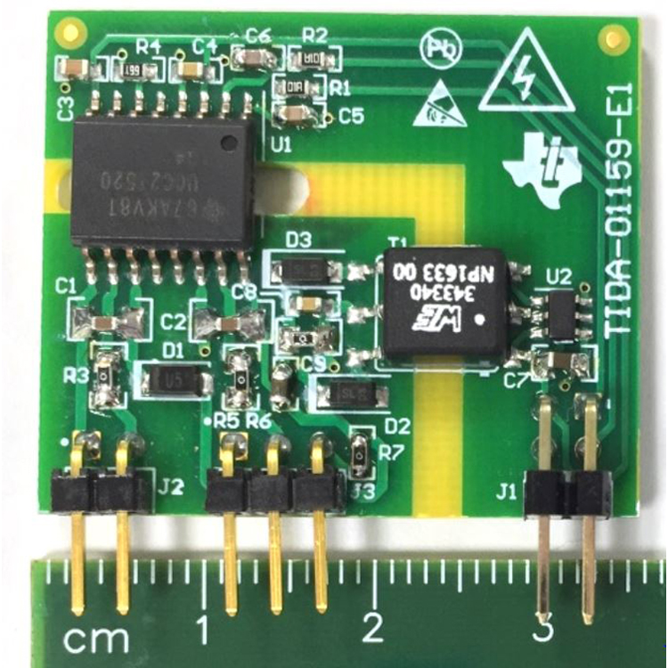
The total power delivered is proportional to the duty cycle. Here, the motor is driven by a square wave with an adjustable duty cycle (the ratio of on time to the period of the signal). The solution to this problem is a method called PWM or pulse width modulation. The biggest drawback with this kind of setup is the efficiency – just like with any other load, the transistor dissipates all the unwanted power. If more current is needed, this circuit can be built discreetly with a few bipolar transistors. This can even be in the form of a variable linear regulator like the LM317 – the voltage across the motor can be varied to increase or decrease speed.


It’s obvious that decreasing the voltage across the motor decreases the speed and a dead battery results in a slow motor but if the motor is powered from a rail common to more than one device, a proper driving circuit is needed. While this kind of setup is good for ‘static’ applications like a miniature windmill or fan, when it comes to a ‘dynamic’ application like robots, more precision is needed – in the form of variable speed and torque control. And running it is as simple as connecting it to two cells – the motor fires up instantly and runs as long as the batteries are connected.


 0 kommentar(er)
